Apollo Sample News
Ryan Zeigler, Apollo Curator
Juliane Gross, Deputy Apollo Curator
Volume 4 No. 2 • September 2022
As of April, all COVID related restrictions for working in the Apollo laboratories have been lifted, and we are fully back in business. Over the past 6 months, a massive amount of progress has been made on the ANGSA project: (1) all gas was extracted from CSVC sample 73001 and initial measurements have been made; (2) all frozen ANGSA samples were processed and allocated; (3) CSVC sample 73001 was successfully scanned by XCT, extruded, completely dissected, samples allocated, and the remainder of the core embedded in epoxy for continuous thin section preparation (which is in progress).
We are pleased to announce that the next Apollo Sample request deadline is Friday November 4th at 5 PM Houston time. Please see the Curation website here, here, and here for more details on the deadline and the submission process. For PIs looking for more information about the samples as they prepare their requests, I highly recommend the Lunar Sample Compendium and the
Apollo Sample and Photo Database. All Apollo sample requests should be emailed directly to me at ryan.a.zeigler@nasa.gov.
The information in this newsletter below will serve as the preliminary catalog for the 73001 gas samples. We invite investigators to submit sample requests for experiments to be performed on these samples as part of the ANGSA gas analysis team, which is led by Dr. Rita Parai. These requests are also due by Friday November 4th at 5 PM Houston time and should be emailed to me directly at ryan.a.zeigler@nasa.gov.
Finally, we expect that the general catalogs for the 73001 and 73002 samples will be released with the spring 2023 Astromaterials Newsletter, and those samples will be available to be requested for the Spring 2023 lunar sample request deadline (likely in May).
Preliminary Catalog information about the Gas Extraction from Sample 73001
During the Apollo 17 mission, astronauts Gene Cernan and Jack Schmitt collected a double drive tube at Station 3 near the rim of Lara crater, just above the Lee-Lincoln Scarp on the South Massif avalanche deposits that extended out onto the Taurus Littrow Valley Floor. This double drive tube consists of a pair of 35-cm long, 4-cm diameter aluminum tubes (Figure 1) that were driven into the lunar surface to collect the regolith with the stratigraphy preserved: upper drive tube 73002 and lower drive tube 73001. Lower drive tube 73001 was placed into a containment vessel called a Core Sample Vacuum Container (CSVC), which was a stainless-steel (SS) tube that was sealed under vacuum on the lunar surface using a metal-knife-edge seal. Upon return to Earth, the CSVC was placed into a N2-purged curation glovebox, placed into a larger more robust stainless steel Outer Vacuum Container (OVC), and the OVC was then pumped down to ~10-2 Torr. Sample 73001 has remained in a N2-purged curation glove box from the time it was sealed until its current use within the ANGSA program.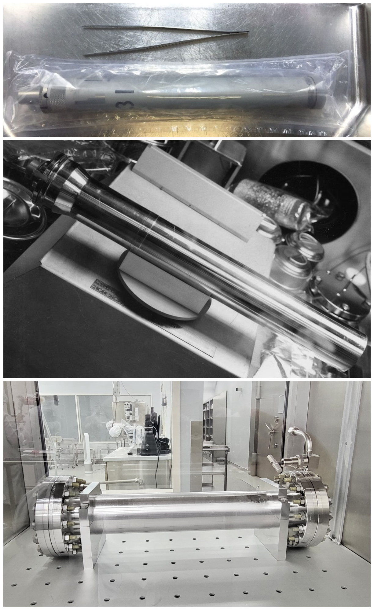
Figure 1: (a) an aluminum drive tube like the one used for 73001 (sealed in Teflon bags under N2 atmosphere); (b) a CSVC inside the Apollo processing cabinet, just like the one that the 73001 drive tube is inside; (c) the 73001 OVC that has the nested Al drive tube and CSVC inside of it.
As part of the ANGSA program, the gas that was in both the 73001 OVC and CSVC were extracted. The OVC had an external valve in place to help facilitate gas extraction, but the CSVC did not have an external valve. Thus, the CSVC had to be pierced to extract the gas. Gas extraction was achieved using two bespoke pieces of equipment that were built for the ANGSA project: (1) a gas extraction manifold built by the Team at Washington University in St. Louis led by Drs. Alex Meshik, Olga Pravdivtseva, and Rita Parai; (2) a piercing device built by a team at ESA led by Dr. Francesca McDonald. Gas was extracted from the OVC and CSVC using differential pressure between those containers and the gas extraction manifold, which typically achieved pressures in the mid 10-9 Torr range (unless otherwise noted). The gas extraction manifold originally had eight ~2-liter SS bottles and two 50 cm3 SS bottles attached to it for storing the extracted gas; a ninth ~1-liter SS bottle was also added to the system before the extraction was completed. See Table 1 for a summary of all gas samples acquired.
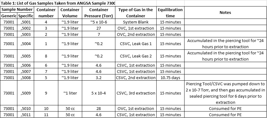
Table 1: A summary of all gas samples acquired.
Two separate gas extractions from the OVC were done (Figure 2). The initial OVC extraction was done with a background manifold pressure of 4 x 10⁻⁶ Torr, an equilibration time of 15 minutes (all equilibration times are 15 minutes unless otherwise stated), and the gas was expanded into one 2-liter bottle and one 50 cm3 bottle. The equilibration pressure observed on gas sample OVC1 was 28 Torr. Just prior to acquiring gas sample OVC1, a system blank was collected under the sample conditions (e.g., similar background manifold pressure and equilibration time). The second OVC extraction was collected into one 2-liter bottle with a background manifold pressure of 5 x 10⁻⁸ Torr; the gas for OVC2 was passed through a tube sitting in a water ice bath during extraction. The equilibrated pressure on OVC2 was 7 Torr.
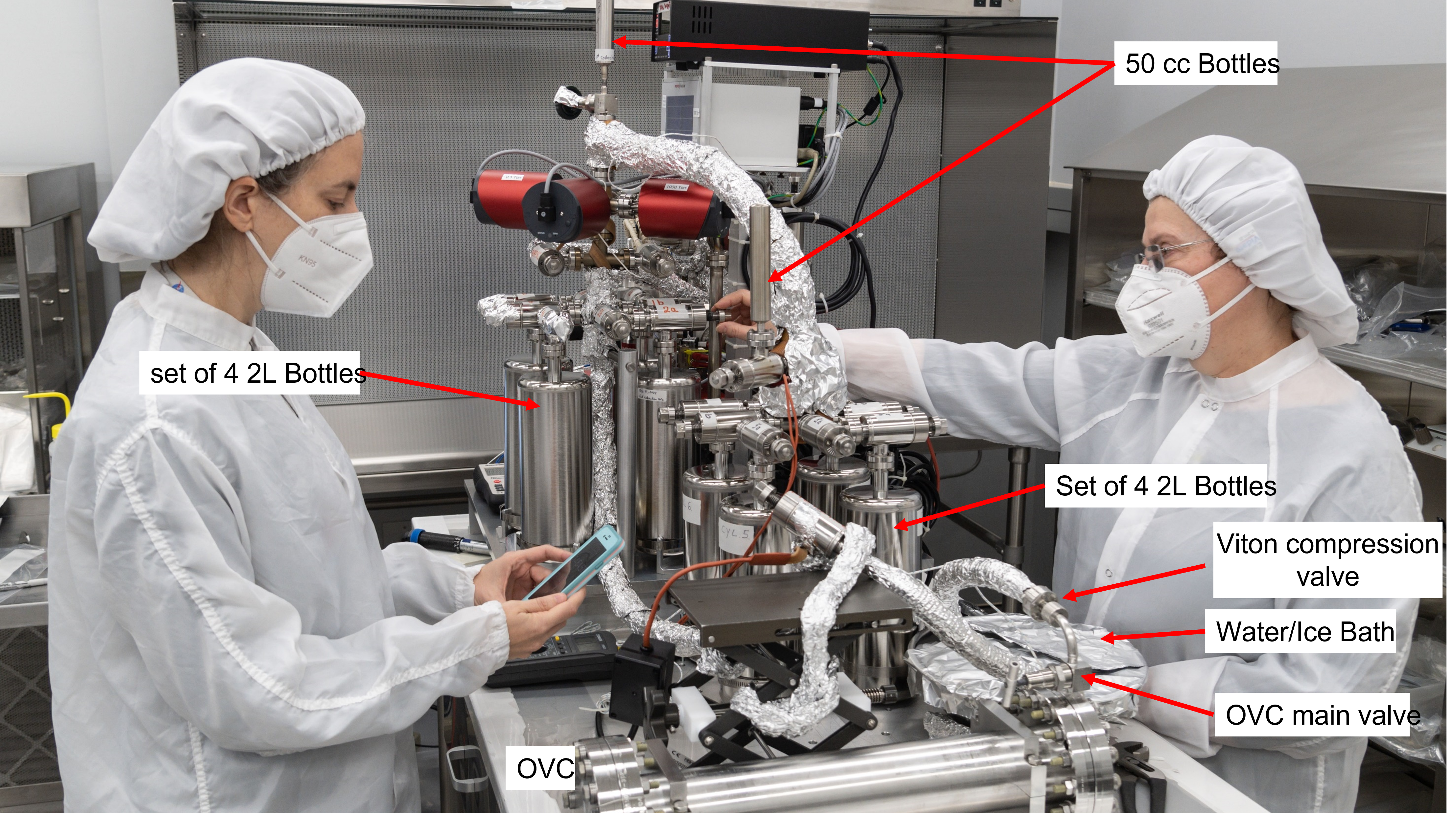
Figure 2: Photo showing the gas extraction manifold with the 73001 OVC attached. The water-ice bath, used to try to remove possible hydrocarbon gas contamination, was only used during OVC2 extraction. Drs. Gross and Pravdivtseva for scale.
After the OVC gas extraction was completed, the OVC was placed back into the N2-purged curation cabinets, the OVC was opened, the CSVC was removed from the OVC, and the CSVC was sealed within the piercing tool (Figure 3). The piercing tool was then removed from the N2-purged cabinets and connected to the gas extraction manifold (Figure 4). The piercing tool was then pumped down by the gas extraction manifold prior to piercing the CSVC to remove the N2 cabinet gas in the piercing tool. During the pump down of the piercing tool over the course of ~48 hours, we were unable to achieve a manifold pressure lower than 10-6 Torr, whereas we could achieve a vacuum of 10-9 Torr in the manifold when the piercing tool was isolated. The RGA analysis of the gas being pumped out of the piercing tool appeared to be nearly pure N2 gas and showed no evidence for atmospheric contamination of the system, nor did multiple He-leak checks of the piercing tool and extraction manifold show evidence of an external leak. Thus, it was decided that there was a slow leak of the CSVC bleeding gas out into the piercing tool.
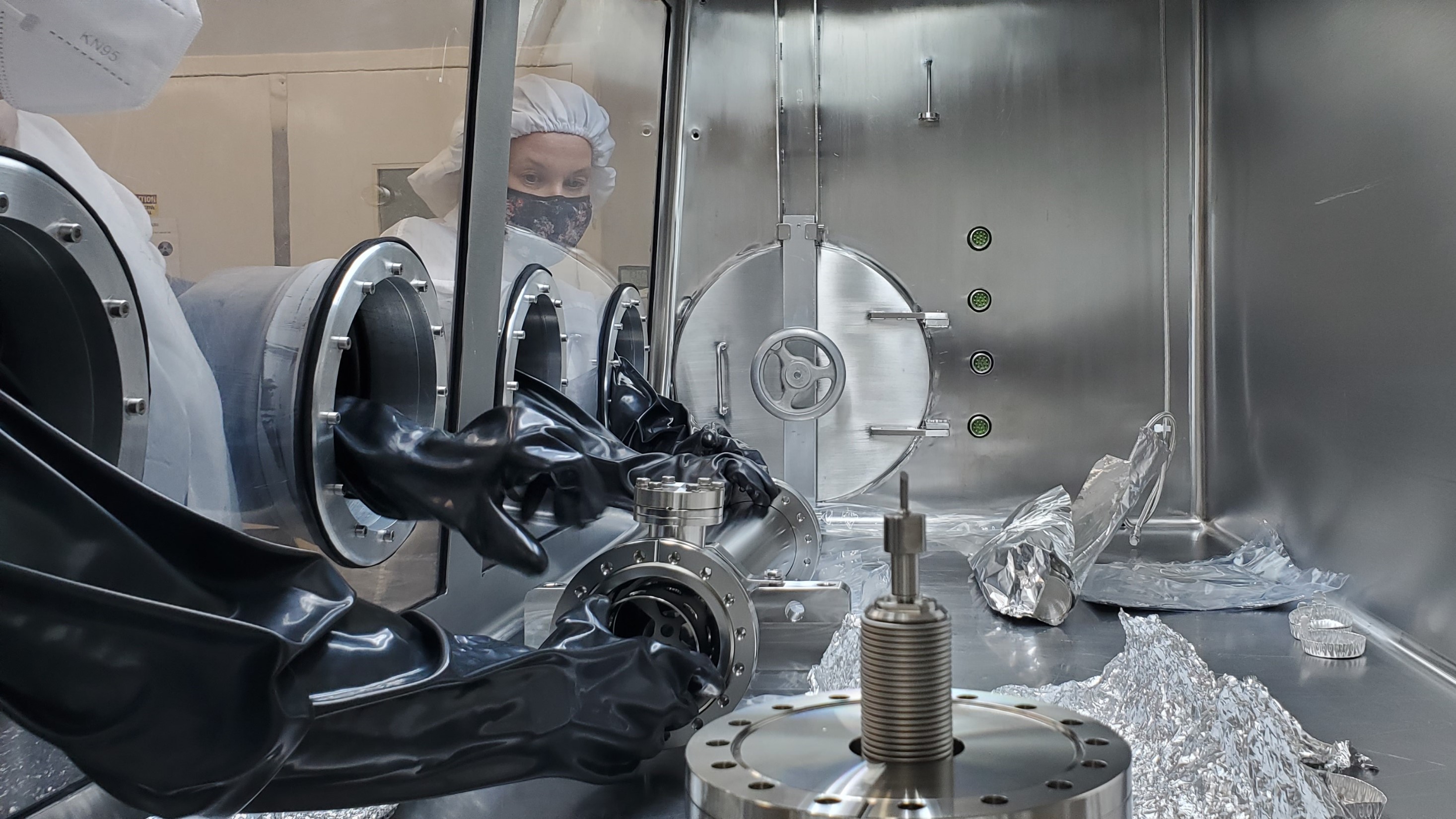
Figure 3: Photos showing the insertion of the CSVC into the Piercing Tool (PT). (a) the CSVC going into the piercing tool insert; (b) the piercing tool insert being placed into the main body of the piercing tool, with the piercing tool top/chisel in the foreground; (c) placing the PT top/chisel on to the PT main body. Drs. Gross and McDonald for scale.
The CSVC "leak gas" was accumulated within the piercing tool for ~24 hours and then collected into one 2-liter bottle with a background manifold pressure of 10-9 Torr (CSVC Leak Gas 1). This process was repeated under almost identical conditions to collect an additional 2-liter bottle of gas as CSVC Leak Gas 2. In both cases, the observed equilibration pressure in the collection bottle for the leak gas samples was ~0.2 Torr. After the CSVC leak gases were collected, the piercing tool was isolated from the manifold, the piercing mechanism on the piercing tool was successfully used to pierce the bottom of the stainless steel CSVC (making a ~2 mm hole), and a first gas extraction from the pierced CSVC was collected in two 2-liter bottles and one 50 cm3 bottle with an equilibration pressure of 4.6 Torr. A second longer gas extraction (CSVC extraction 2) was performed with an equilibration time of 10.75 days, with a final equilibration pressure of 3.2 Torr. Finally, the gas extraction manifold was used to pump down the CSVC/piercing tool to a pressure of 2 x 10⁻⁷ Torr. The piercing tool was then isolated for 6 days, and a final CSVC extraction 3 was collected into a single 2-liter bottle with a final equilibration pressure of 5 x 10⁻⁴ Torr.
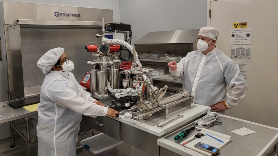
Figure 4: Photo showing the gas extraction manifold with the piercing tool (with the 73001 CSVC inside). Drs. Parai and Zeigler for scale.
The two 50 cm3 bottles of gas (OVC1; CSVC1) were subsampled and portions of each distributed for preliminary analyses to ANGSA Team members Dr. Zachary Sharp at the University of New Mexico and Dr. Rita Parai at Washington University in St. Louis. Dr. Sharp's results showed that the vast majority of gas within both the OVC and CSVC is N2, and thus there is little evidence for laboratory atmosphere contamination within the samples. The δ15N value of -4.4‰ relative to air, generally consistent with the gas used in our N2 purged cabinets, but suggesting that 14N has preferentially leaked into the system from the cabinet. The CSVC sample has a lower absolute concentration of N2 than the OVC sample (98.3% vs. 99.9%), suggesting that some of the H2O, H2, and Ar within the CSVC could be indigenous in origin (though some of the H2 would have exsolved from the SS over the years of storage; more details here). Similarly, Dr. Parai's results for major gas phases measured by RGA showed that N2 was the dominant gas (presumably curation cabinet gas), with measurable CO2 and H2 gas (likely exsolved from the SS containers), and no evidence of significant contamination of the OVC or CSVC gas from laboratory air. Additionally, although there was some evidence of a terrestrial component in some of the noble gas measurements from the CSVC1 sample, there was also clear evidence of a solar wind component apparent in both the Ne and Ar isotopes (more details here).
Currently, all nine 1- or 2-liter bottle gas samples listed in Table 1 are attached to the gas extraction manifold, which is being maintained at low 10-9 Torr pressure (Figure 5). Each bottle is double valved with a "between valve" volume of ~37 cm3. *Requesting PIs will need to provide their own pre-conditioned gas sample bottles for allocation of gas samples. Sample containers should be stainless steel and bakeable to 200 °C. Containers should be equipped with two valves - either bellows or all-metal bakeable valves, with a 1.33" conflat flange to connect to distribution ports. Requesting PIs should determine the internal volume of their container(s) prior to sending to JSC.
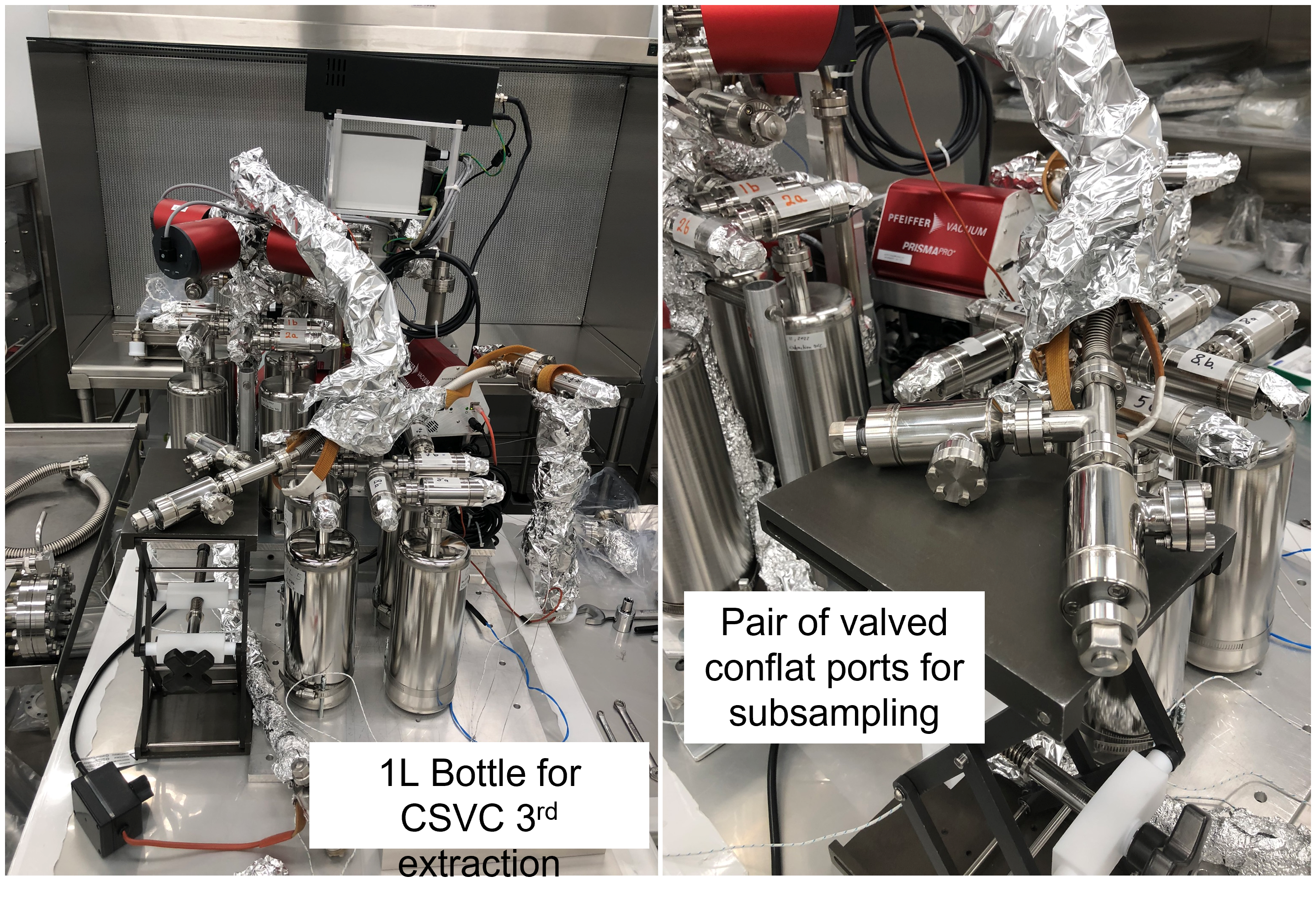
Figure 5: Current configuration of the Gas Extraction Manifold showing the additional SS 2-liter bottle added to the system, as well as the two available conflat distribution ports for PI subsamples to be taken through. No doctors for scale.